


Principles of computer-aided engineering of thermoplastic injection molding: Process settings
Igor Barvinsky (CSoft)
CADmaster. 2015. No. 2. P. 70–77.
To simulate injection molding of thermoplastic materials, one needs to determine process conditions of simulation. These are similar to process settings of control systems of injection molding machines and auxiliary equipment, but can differ significantly from these settings in some cases. Correctly set process conditions and known differences between simulation parameters and actual injection molding settings are of great importance: they help explaining simulation data properly during defects prediction or scrap causes analysis, and implementing simulation process modes in actual injection molding.
The following are the main process settings for 3D simulation of thermoplastic injection molding using Moldex3D R13 software by CoreTech System [1].
Process Wizard
One can define injection molding process settings in Process Wizard (Fig. 1) of Moldex3D by several methods. CAE mode is used when desired injection molding machine characteristics are determined through simulation. Machine modes (by time or by flow rate profile) assume that one knows the model of injection molding machine. You can either select a model from Moldex3D database or set machine characteristics prior to simulation.
 |
|
Fig. 1. Moldex3D Process Wizard. |
For some injection molding machines, process can be set in Moldex3D just as it is set in the machine PLC. In this case, Process Wizard shows full PLC interface (Fig. 2).
 |
|
Fig. 2. PLC interface of Fanuc-S2000i injection molding machine in Moldex3D Process Wizard. |
Process settings for injection phase
Volumetric flow rate (corresponding to linear velocity of translational screw motion) is one of the most important process settings of thermoplastic injection molding. Flow rate affects the level of heat dissipation in polymer melt under shear flow in runner system channels and mold cavity, and determines the temperature of melt front for a given small or medium thickness part design. For reduced wall thicknesses, one must increase flow rate to compensate (by increasing melt heat dissipation) the increased heat loss during melt flow. In thick mold cavities, cooling rate of inner layers is extremely small, and heat dissipation under shear flow of melt is negligible. Therefore, injection rate has no significant effect on the temperature of melt flow front for thick-walled parts.
Flow rate affects the appearance and the layered structure of molded part, thermal and orientational residual stress, shrinkage, mechanical and other quality characteristics of injection molding part [2]. A too high or too low flow rate can cause various types of unstable filling [3] and other problems.
Process Wizard sets flow rate in the same manner as in actual injection molding machines, with a stepwise (Fig. 3) or a linear flow rate profile. In the latter case, a so-called polyline is used to build a profile. Moldex3D automatically takes into account melt compression in heating cylinder during injection.
 |
|
Fig. 3. Setting a stepwise flow rate profile |
Injection pressure, corresponding to maximum pressure at injection phase, is set as a profile both in actual injection molding and in simulation environment. In actual production, injection pressure is set to prevent the so-called peak pressure, of high risk while setting the injection process and during production with a highly instable resin rheology. When performing simulation, for most tasks one can set the injection pressure equal to 100 % of the maximum permissible pressure during injection, which is estimated based on the maximum pressure of the injection molding machine considering its wear and model (e.g. with or without a runner system).
As at the injection phase under normal process conditions (with no flow instability and no air captured in mold cavity), melt pressure at flow front equals atmospheric pressure, maximum injection pressure equals pressure drop along the flow path. The dependence of maximum injection pressure on flow rate (for a wide range of flow rates) has a minimum (Fig. 4). Pressure drop in the first part of the diagram is due to decreasing thickness of solidified melt layer adjacent to the wall (resulting from increased dissipation at melt flow), while pressure increase in the second part is mostly linked to higher shear stress at high shear rates [4].
 |
|
Fig. 4. Maximum injection pressure (Pmax) versus volumetric injection rate (Vinj) with pressure drop (1st part) and increase (2nd part) intervals; flow rate optimum range (V1 to V2). |
For simulation, melt temperature is set as constant for the enter of mold cavity, gate or runner system, or at shot start (in the pre-nozzle area of heating cylinder of injection molding machine), depending on which of these areas are represented in model. By default, it corresponds to melt temperature recommended by the manufacturer of thermoplastic material and normally equals the average point of the melt temperature range.
Moldex3D database contains temperature ranges for thermoplastic material processing as per the manufacturers' recommendations. As no common methods for determining minimum and maximum melt temperatures exist, a complex approach taking into account production experience and data on rheology behavior, stability of chemical structure and composition, and performance of finished parts allows to estimate these temperatures.
At molding of a particular part, melt temperature range ensuring part quality is in fact much narrower than the recommended temperature range.
Melt temperature has a great influence on simulation results, especially for materials with highly temperature-sensitive viscosity. For such materials, temperature increase leads to a significantly increased melt flow length in mold cavity. In general, higher melt temperatures help making weld lines less visible and reducing residual stress but may cause thermal oxidative destruction of materials with low thermal stability. To prevent material destruction, one must consider the stay of thermoplastic material at processing temperature and melt temperature control features in actual injection process when setting melt temperature.
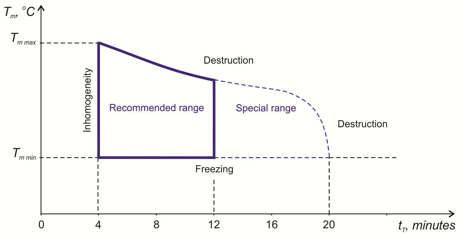
Fig. 5 gives a typical melt temperature versus residence time at processing temperature diagram for injection molding thermoplastics of relatively high thermal stability and indicates specific problems of plasticizing phase.
 |
|
Fig. 5. Melt temperature (Тm) versus residence time at processing temperature (tT) for injection molding of thermoplastics with relatively high thermal stability and specific problems of plasticizing phase; Tm min is the minimum melt temperature, Tm max is the maximum melt temperature (based on [5]). |
To ensure thermal homogeneity of melt, residence time in heating cylinder shall exceed four minutes. [5] For thermoplastics with low thermal stability (e.g. unplasticized PVC, thermoplastic polyurethane, homopolymer of formaldehyde, etc.), maximum residence time at the lowest recommended processing temperature shall be 6 to 10 minutes.
Total residence time of thermoplastic material at high temperature (high-temperature residence time) consists of its residence time in screw channels, in pre-nozzle area of barrel at the plasticizing, injection and packing phases, and in hot runner system. High-temperature residence time may be significantly longer if the maximum shot volume of injection molding machine far exceeds the shot volume required to produce the specific part (including packing phase), and if the total volume of items produced in a mold far less the volume of hot runner system.
The summary page of Process Wizard displays an estimated residence time of thermoplastic material in hot runner system.
Melt temperature concept is widely used in literature, but in an actual injection molding process with standard machine configuration, only heating cylinder temperature near its inner surface is monitored, while actual melt temperature in screw channels and pre-nozzle area depends on many factors. Melt temperature inside a barrel varies considerably depending on position both along barrel length and in transversal direction, as well as in time.
These temperature variations are affected by screw design, plasticizing conditions (screw speed, back pressure), properties of granulated and molten thermoplastic material, screw wear, injection conditions, part and mold design [2]. Actual thermoplastic melt temperature during plasticizing can substantially exceed a set temperature (by 5 to 20 °С or even more). For this reason, the "special range" shown in Fig. 5 does not allow in most cases to obtain quality parts if one only monitors the temperature based on heating cylinder zones.
Fig. 6 shows some injection molding problems related to melt temperature at enter of mold cavity and to maximum pressure during injection. Reduced maximum injection pressure or melt temperature lead to short shot, whereas high maximum injection pressures lead to flash due to high average pressure in mold cavity. The lower part of temperature range does not allow for normal weld line quality, reduces part gloss (when using polished shaping components) or leads to defects and other problems of part surface texture.
 |
|
Fig. 6. Melt temperature (Тm) versus maximum injection pressure (Pmax) and typical injection problems; Tm min is the minimum melt temperature, Tm max is the maximum melt temperature. |
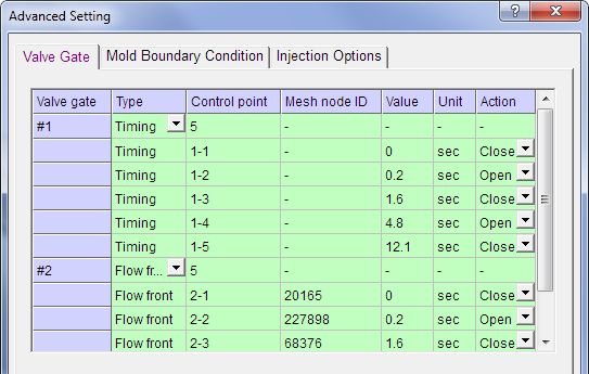
When using hot runner nozzles with shutoff gates for actual injection molding and its simulation in Moldex3D, there are additional process settings providing control of opening and closing modes of each nozzle. In molds for cascade (sequential) injection molding, injection process usually begins using one nozzle, while other groups of nozzles only open after flow front passes the corresponding gate locations (Fig. 7).
 |
|
Fig. 7. Process settings dialog for hot runner nozzles with shutoff gates (sequential injection). |
Control points at simulation conditions (Fig. 7) give times corresponding to the initial state and nozzle opening/closing actions at filling and packing phases. When setting nozzle opening by flow front, you set a period starting from the passage of flow front at a given mesh node (detected automatically) before a nozzle opens.
The most important injection molding process settings include the time of switching from flow rate control mode to that of injection pressure control [4, 5]. This parameter has a great influence on the nature of pressure changes in mold cavity (Fig. 8) and defines the end of injection phase (the period from the beginning of injection to the switching time is called injection time).
If you switch tardily to pressure control mode at a set injection pressure, you get a peak pressure (Fig. 8b) that leads to flash, less accurate part dimensions and increased residual stress in the part, and quite often causes damage to the mold by hydraulic impact.
A too early switching to pressure control mode leads to a sharp pressure drop in the mold: there is a local pressure maximum (Fig. 8c) at the graph of cavity pressure versus time. The rest of the cavity is filled at a melt flow rate determined by a given packing pressure profile. At constant packing pressure, melt flow rate drops, leading to a decrease of melt front temperature due to lower heat dissipation in the melt. The latter negatively affects part quality and may result in a short shot.
 |
|
Fig. 8. Mold cavity pressure (Рcav) versus time (t) from the injection start on for a normal (a), a tardy (b) and a too early (c) switching to packing pressure [5]. |
In production, several ways of switching to pressure control mode are used [4, 5]. The most commonly used is switching by screw position, which provides highly accurate injection shots for thermoplastic materials with stable rheology.
For simulation, switch-over time can be set either as a molding volume percentage or by screw position (if one performs simulation for a specific injection molding machine). Switch-over time normally corresponds to 98...99 % of molding volume.
Process settings for packing phase
Both for an actual injection molding process and when simulating packing phase, pressure profile is set either stepwise or linearly in time (Fig. 9). Packing pressure at each step may be set as an absolute or a relative (to maximum packing pressure) value.
 |
|
Fig. 9. Setting a packing pressure profile with linear pressure decrease. |
Initial packing pressure determines melt flow rate in mold cavity at filling phase after switching to pressure control mode. A low initial packing pressure during injection molding of large, thin-walled and other parts can lead to cooling of melt front and, hence, cause surface defects, high residual stress and other issues. A too high initial packing pressure results in a high melt flow rate when finishing mold cavity filling, which can also cause high residual stress and other problems.
Fig. 10 gives packing time versus packing pressure diagram and indicates typical packing issues.
 |
|
Fig. 10. Packing time (tpack) versus packing pressure (Ppack) diagram and packing issues. |
Packing time is normally set to be slightly greater than the time before mold cavity is disconnected from heating cylinder. In many cases (e.g. for cold runner multicavity molds), mold cavity is disconnected at the time when gates are solidified. One can determine this time automatically or manually by several methods: by stabilization of part weight in time, by sharp reduction of melt flow through a gate, etc.
Increased packing pressure reduces volumetric shrinkage, which improves packing of relatively thick-walled areas, especially when they are located far from a gate. At the same time, a high packing pressure can lead to negative consequences such as over-packing of relatively thin-walled sections (primarily those located near a gate), higher residual stress and other problems [6].
One selects the type of packing pressure profile (with a constant pressure or a pressure decrease) based on part design, gate location and properties of thermoplastic material. Lower packing pressures when finishing packing phase reduce uneven part packing along its length, but may increase crystallization irregularities for crystallizing materials, which increases uneven shrinkage, causes warpage and high residual stress.
Process settings for mold heating and cooling
The simplest option when simulating molding cooling process in Modex3D is to set a uniform mold temperature.
Mold temperature increase within the range recommended by a thermoplastic material manufacturer allows for greater melt flow lengths in mold cavity, reduced cooling rate and, hence, increased surface quality and reduced residual stress. This enhances cracking resistance of amorphous materials with high glass transition temperature (e.g. polycarbonate) and dimensional stability of molded parts during their storage and operation, but leads to increased process shrinkage. One of the issues linked to high mold temperature are visible ejector pin marks and local deformations in areas with difficult heat removal ("hot spots") typically emerging close to high ribs. Reduced mold temperatures affect negatively the appearance and strength of weld lines, especially for thin-walled parts.
If one simulates mold cooling process taking into account cooling channels design in steady or unsteady conditions (for average or changing injection cycle temperature, respectively), process settings include coolant temperature and flow rate (the latter if a flow-meter is available in production) determined for mold temperature regulator (Fig. 11). Flow rate of coolant is set to ensure turbulent coolant flow in cooling channels (recommended Reynolds numbers: 5,000 to 10,000).
 |
|
Fig. 11. Process settings for mold cooling channels and heaters of a hot runner system. |
Cooling time counts from the end of packing time to the beginning of mold opening. As a rule, one sets cooling time to ensure molded part is cooled down to a required ejection temperature (as specified in the database among the specific material properties). A too early part removal from the mold results in part warpage. However, one can normally remove thick-walled items with sufficiently high rigidity (produced from a thermoplastic material with high modulus of elasticity) from the mold without waiting for their full interior solidification. A notable exception is parts with high dimensional precision requirements.
Increased cooling time reduces warpage of parts (thanks to stress relaxation), but reduces injection molding equipment performance, making cycles longer.
When simulating mold preheating (this simulation is available for unsteady conditions), process setting is the time of mold heating from ambient temperature to operating one.
When simulating thermal processes in a hot runner system, Advanced Hot Runner module accounts for the design of heaters, metal parts of hot runner nozzle and manifold, thermal insulation area and thermal sensors location, as well as for temperature control method (by temperature, by heater power or using PID control). If first two cases, process settings include temperature (Fig. 11) or heater power, respectively. In case of PID control, one sets target temperature and gain factors.
Moldex3D Process Wizard allows for setting several steps of mold heating and cooling during an injection molding cycle for an unsteady mode simulation, which makes it possible to simulate injection molding process using a variety of temperature control methods. This provides, in particular, simulation for variotherm injection molding. The mold is kept at an elevated temperature (greater than the ejection temperature for thermoplastic material) during injection and packing, while at molding cooling phase, mold temperature decreases to below the ejection temperature. Variotherm injection molding allows for enhancing part surface quality and weld lines appearance without sacrificing injection equipment performance.
Plasticizing phase simulation
Moldex3D includes ScrewPlus module (jointly developed by Compuplast International and CoreTech System) designed to simulate and optimize thermoplastic plasticizing phase, as well as to take into account the effect of process settings at this phase on melt temperature. Calculation for a standard screw includes simulation of granulate melting, mass and heat transfer in feeding, compression and metering zones for specific plasticizing process mode and screw design and given the properties of thermoplastic material. Special screw simulations are also available, including those for barrier screws, screws with a mixing zone, etc.
Process settings for a plasticizing phase simulation include zone temperatures of heating cylinder, screw speed and back pressure. One can use results of melt temperature simulation at plasticizing phase as input data for an injection phase simulation.
Optimization of process settings
The diagrams shown in Fig. 5, 6 and 10 are simplified representations of the "processing window" of thermoplastic material, a hypothetical range of conditions providing the required product quality. One can only obtain such diagrams when freezing the other process parameters. In actual injection molding, diagrams for two and even three factors do not provide complete information on acceptable range of process conditions due to parameter interaction and the complexity of defect formation mechanisms.
Quality characteristics of parts produced by injection molding, although dependent on process settings, are largely determined by local resin conditions (temperature, pressure, flow rate and direction, cooling rate, etc.) in a specific area of mold cavity. These characteristics change significantly when passing from one area to another because of heat dissipation at melt flow, melt compressibility and viscoelasticity, changing geometric conditions (wall thickness and other design features), uneven cooling and other factors.
Injection molding includes complex structural processes such as crystallization (for crystallizing thermoplastics), destruction and orientation of fibrous fillers, or uneven distribution of fibrous and particulate fillers due to melt flow, all of which have a very large impact on product quality. Moldex3D can help with simulating these processes as well. Flow and cooling conditions cause the formation of layered structure of molded parts.
You can find process settings ensuring high product quality and optimize process mode for one or several quality characteristics by performing simulation in a few steps. Their content and sequence depend on task features: specific thermoplastic material, part and mold design, requirements for dimensional accuracy, etc.
Initially, one usually performs a test simulation at typical process conditions, which provides the necessary information to select the main process settings.
One of the initial phase tasks is to evaluate which flow rate will provide a thermal balance for melt flow in mold cavity with a basic wall thickness. In most cases, flow rate affects all the other injection process characteristics significantly [2].
Moldex3D includes several methods aimed at optimizing injection molding process settings. For quick evaluations, one can use algorithms of automatic determination of flow rate and packing pressure profiles by simply pressing Profile Advisor... button in Process Wizard (Fig. 3 and 9). These algorithms employ data from previously performed simulations for the same mold and thermoplastic material grade.
Expert module provides a rating of process settings that affect output process characteristics, and helps finding an optimum injection molding mode using design of experiments techniques.
The author would like to thank CoreTech System for the information provided.
Literature
1. CoreTech System Co., Ltd. http://www.moldex3d.com
2. Barvinsky I. A., Barvinskaya I. E. Application of the Flow Rate Profile for Elimination of Thermoplastic Injection Molded Part Defects. Seminar «Thermoplastics Injection Molding: Economic Efficiency and Quality». Moscow. October 24, 2012. Preprint. — 9 pages.
3. Barvinsky I. A., Barvinskaya I. E. Problems of Polymeric Materials Injection Molding: Unstable Mold Filling. // Polymeric Materials. 2009. Vol. 8. — P. 14–21.
4. Kalinchev E. L., Kalincheva E. I., Sakovtseva M. B. Plastic Injection Molding Equipment: Calculation and Design. — Moscow: Mashinostroenie. 1985. 256 pages.
5. Johannaber F. Injection Molding Machines. A User's Guide. Translated from English, editor: E. L. Kalintchev. — Saint-Petersburg: Professiya. 2009. 400 pages.
6. Barvinsky I. A., Barvinskaya I. E. Problems of Polymeric Materials Injection Molding: Packing. // Polymeric Materials. 2014. Vol. 3. — P. 3–13.
